 سوئیچ شبکه
 انتقال خطوط تلفن
 ماژول فیبرنوری
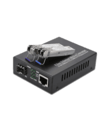 مبدل های فیبرنوری
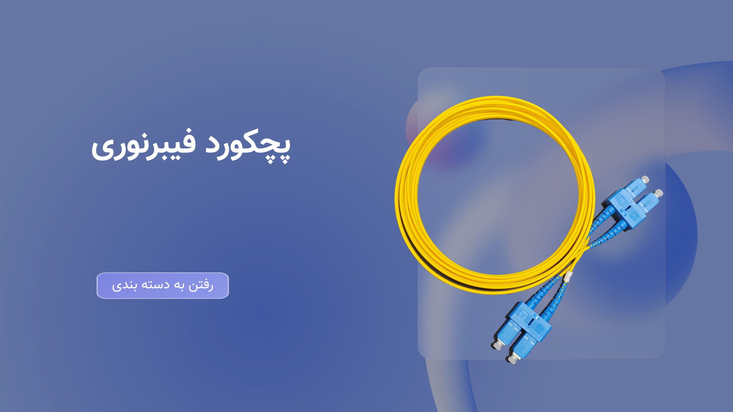 پچکورد و پیگتیل فیبرنوری
علاقه مندی ها
اشتراک گذاری

نقد و بررسی
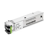
The central wavelengths of the 4 CWDM channels are 1271, 1291, 1311 and 1331 nm as members of the CWDM wavelength network defined in ITU-T G694.2. It consists of a duplex LC connector for the optical interface and a 38-pin connector for the electrical interface.
This product is designed according to the QSFP Multisource Agreement (MSA) form factor, optical/electrical connection and digital detection interface. It is designed to be used in the harshest outdoor operating conditions including temperature, humidity and EMI interference.
QSFP-40-ER module works with +3.3V power supply and LVCMOS/LVTTL global control signals such as current state, reset, interrupt and low power are observed with the modules. A 2-wire serial interface is designed to send and receive control signals and obtain digital diagnostic information.
Capabilities
- 4 CWDM lanes MUX/DEMUX design
- Up to 11.2Gbps per channel bandwidth
- Aggregate bandwidth of > 40Gbps
- Duplex LC connector
- Compliant with 40G Ethernet IEEE802.3ba and 40GBASE-ER4 Standard
- QSFP MSA compliant
- APD photo-detector
- Up to 40 km transmission
- Compliant with QDR/DDR Infiniband data rates
- Single +3.3V power supply operating
- Built-in digital diagnostic functions
- Temperature range 0°C to 70°C
- RoHS Compliant Part
Use cases
- Rack to rack
- Data centers Switches and Routers
- Metro networks
- Switches and Routers
- 40G BASE-ER4 Ethernet Links
Technical specifications
- Optical Parameters(TOP = 0 to 70 °C, VCC = 3.0 to 3.6 Volts)
| Parameter | Symbol | Min | Type | Max | Unit | Ref. |
| Transmitter | ||||||
|
Wavelength Assignment | L0 | 1264.5 | 1271 | 1277.5 | nm | |
| L1 | 1284.5 | 1291 | 1297.5 | nm | ||
| L2 | 1304.5 | 1311 | 1317.5 | nm | ||
| L3 | 1324.5 | 1331 | 1337.5 | nm | ||
| Side-mode Suppression Ratio | SMSR | 30 | – | – | dB | |
| Total Average Launch Power | PT | – | – | 8.3 | dBm | |
| Average Launch Power, each Lane | -7 | – | 8 | dBm | ||
| Difference in Launch Power between any two Lanes (OMA) | – | – | 6.5 | dB | ||
| Optical Modulation Amplitude, each Lane | OWN | -4 | +3.5 | dBm | ||
| Launch Power in OMA minus Transmitter and Dispersion Penalty (TDP), each Lane | -4.8 | – | dBm | |||
| TDP, each Lane | TDP | 2.3 | dB | |||
| Extinction Ratio | IS | 3.5 | – | – | dB | |
| Transmitter Eye Mask Definition {X1, X2, X3, Y1, Y2, Y3} | {0.25, 0.4, 0.45, 0.25, 0.28, 0.4} | |||||
| Optical Return Loss Tolerance | – | – | 20 | dB | ||
| Average Launch Power OFF Transmitter, each Lane | Poof | -30 | dBm | |||
| Relative Intensity Noise | Also | -128 | dB/HZ | 1 | ||
| Optical Return Loss Tolerance | – | – | 12 | dB | ||
| Receiver | ||||||
| Damage Threshold | THd | 3.3 | dBm | 1 | ||
| Average Power at Receiver Input, each Lane | R | -20 | -7 | dBm | ||
| Receive Electrical 3 dB upper Cut off Frequency, each Lane | 12.3 | GHz | ||||
| RSSI Accuracy | -2 | 2 | dB | |||
| Receiver Reflectance | Rrx | -26 | dB | |||
| Receiver Power (OMA), each Lane | – | – | 3.5 | dBm | ||
| Receive Electrical 3 dB upper Cutoff Frequency, each Lane | 12.3 | GHz | ||||
| LOS De-Assert | THED | -25 | dBm | |||
| LOS Assert | THEA | -35 | dBm | |||
| LOS Hysteresis | THEH | 0.5 | dB | |||
Produced models
| 40G- 40km QSFP optical module | SFP 10G Single-Mode 20km optical module |
| 6.25G Multimode SFP Optical Module | SFP-10G Single-Mode 10km optical module |
| SFP-10G-BX optical module | SFP-10G Single-Mode 80km optical module |
| SFP-10G-ZR optical module | SFP-10G Single-Mode 40km optical module |
| SFP-10G-LR-20KM optical module | SFP-10G LR Single-Mode 10km optical module |
| sfp 10G SR optical module | SFP-10G Multi-Mode 300M Optical Module |
| SFP-10G Single-Mode 60km optical module | |
| FSP-1 0G BX LC SMF 40km 1330nm optical module |
پرسش و پاسخ
0 پرسش و پاسخ
پرسش و پاسخی وجود ندارد